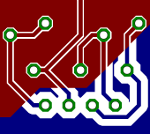
 After a few years of abstinence I designed a printed-circuit board again using Eagle. After that I printed out the design, exposed the board to UV light, etched, and drilled it. Everything went pretty well until I started the actual soldering. The restrings–the green circles in the image–were too small which made it awfully hard to achieve a solder connection between them and the components’ wires. Instead I inadvertantly connected the PCB traces with the ground plane all the time because they were too close to each other. If only I had looked at old designs before to see what design rules I had used back then to adapt the Eagle output to my less precise DIY manufacturing process. Next time make sure to use settings like these:
- Set the isolate parameter of polygons to at least 16 mil ≈ 0.4 mm. Better even use 32 mil.
- To increase the size of restrings go to DRC → Restring and increse the minimum for Top and Bottom Pads from 10 mil to 15 mil.